| information extension spring
calculation |
|
This spring design program was
created on the basis of the German standard for springs as well as our
experience in production engineering. The computation can be carried out for
compression, extension and torsion springs. The procedures use the same input
logic typical for Windows, i.e. via keyboard and mouse.
No warranty is accepted for calculation results
outside the production at "Gutekunst Federn". |
| pre-setting extension
spring calculation |
Material, quality category as
per DIN 2097, loop shape and a valid combination of diameter, spring forces,
spring deflections and lengths must be entered in the parameter pre-settings.
|
Standard combinations include i.e.:
|
 Material, De or Di, F2, R Material, De or Di, F2, R |
 Material, De or Di, F2, R, L0 Material, De or Di, F2, R, L0 |
 Material, De or Di, F2, s2 Material, De or Di, F2, s2 |
 Material, De or Di, F2, s2, F1 or
s1 Material, De or Di, F2, s2, F1 or
s1 |
 Material, De or Di, F2, L2, L0 Material, De or Di, F2, L2, L0 |
 Material, De or Di, F2, L2, F1 or
L1 Material, De or Di, F2, L2, F1 or
L1 |
 Material, d, De or Di, L0, L2, n Material, d, De or Di, L0, L2, n |
|
 material properties material properties |
Designation,
Material-description
|
Max. operating
temp. |
EN |
F
(AFNOR) |
GB
(BS) |
S
(SIS) |
USA
(AISI) |
| G-module |
EN 10270-1 type SM
Spring steel wire
For all common springs |
80°C |
10270-1 |
NFA
47-301-76 |
BS 5216-75 |
* |
AMS
5112 |
| 81500 |
EN 10270-1 type SH
Spring steel wire
For all common springs |
80°C |
10270-1 |
NFA
47-301-76 |
BS 5216-75 |
* |
AMS
5112 |
| 81500 |
EN 10270-1 type SH and DH
Spring steel wire
For all common springs |
80°C |
10270-1 |
NFA
47-301-76 |
BS 5216-75 |
* |
AMS
5112 |
| 81500 |
EN 10270-2 / VDC
(unalloyed)
Valve spring wire
In high dynamical stress |
80°C |
10270-2 |
* |
* |
* |
* |
| 79500 |
EN 10270-2 / VDSiCr
(alloyed)
Valve spring wire
In high dynamical stress between 80 and 120° C |
120°C |
10270-2 |
* |
2803 685A55HD |
* |
6150 |
| 81500 |
1.4310 /
X10CrNi188
Stainless steel V2A
High corrosion resistance |
270°C |
10270-3 |
Z12CN17.07 |
301S21 |
2330 |
302 |
| 73000 |
1.4568 /
X7CrNiAI17-7
Spring steel V4A
Minimal relaxation, high dynamical stress |
350°C |
10270-3 |
Z8CNA17.07.01 |
301S81 |
2388 |
631 |
| 78000 |
CW507L / CuZn36
Copper wire
Non-magnetic, salt-water proof |
60°C |
12166 |
* |
* |
* |
* |
| 35000 |
CW452K / CuSn6
Bronze alloy
Non-magnetic, solderable, weldable, corrosion
resistant |
60°C |
12166 |
* |
* |
* |
* |
| 39000 |
|
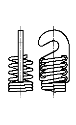
 loop shapes loop shapes |
When making your
selection, please note the constructional limitations of certain loop
shapes.
< Lh > = distance of
inner edge of loop from the spring body (mm)
< Di > = inner coil diameter (mm)
|
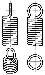
1/1 German
loop
Make input for "Lh" and
"m"
(Lh = 0,8 up to 1,1 Di) |
 |
|
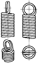
1/1 douple
German loop
Make input for
"Lh"
(Lh = 0,8 up to 1,1 Di) |
 |
|
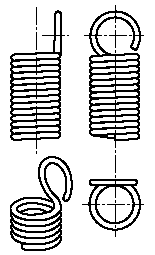
1/1 German
side loop
Make input for
"m"
(Lh ~ Di) |
 |
|
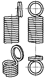
1/1 double
German side loop
No more
input
(Lh ~ Di) |
 |
|
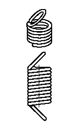
1/1 German
loop, aslant
Make input for
"m" |
 |
|
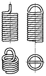
1/2 German
loop
Make input for "Lh" and
"m"
(Lh = 0,55 up to 0,8 Di) |
 |
|
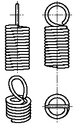
English
loop
Make input for"m"
(Lh ~
1,1 Di) |
 |
|
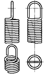
Hook
no
constructional limitation |
 |
|
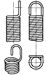
Extended side
hook
no constructional
limitation |
 |
|
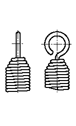
Coiled-in
hook
no constructional
limitation |
 |
|
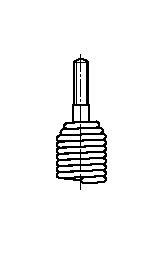
Screwed
plug
no constructional
limitation |
 |
|
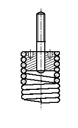
Screwed
no
constructional limitation |
 |
|
Screwed-in
shackle
no constructional
limitation |
 |
|
|
|
|
| You have 4 possibilities
for entry: |
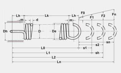
 all calculation pre-settings all calculation pre-settings |
Here, all entry windows
for the calculation are available.
|
|
| Di = inner coil
diameter (mm) |
| De = outer coil
diameter (mm) |
| F0 = initial
tension (N) |
| F1 = prestressed
spring force (N) |
| F2 = loaded
spring force (N) |
| s1 = prestressed
spring deflection (mm) |
| s2 = loaded
spring deflection (mm) |
| R = spring rate
(N/mm) |
| L0 = unstressed
spring length (mm) |
| L1 = prestressed
spring length (mm) |
| L2 = loaded
spring length (mm) |
|
 calculation according to paths and
forces calculation according to paths and
forces |
In this case for a better overview, only the windows
for the calculation according to paths and forces are
available.
|
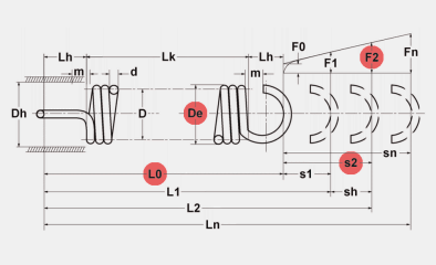 |
| Di = inner coil
diameter (mm) |
| De = outer coil
diameter (mm) |
| F0 = initial
tension (N) |
| L0 = unstressed
spring length (mm) |
| s1 = prestressed
spring deflection (mm) |
| F1 = prestressed
spring force (N) |
| s2 = loaded
spring deflection (mm) |
| F2 = loaded
spring force (N) |
|
 calculation according to lengths and
forces calculation according to lengths and
forces |
In this case for a better overview, only the windows
for the calculation according to lengths and forces are
available.
|
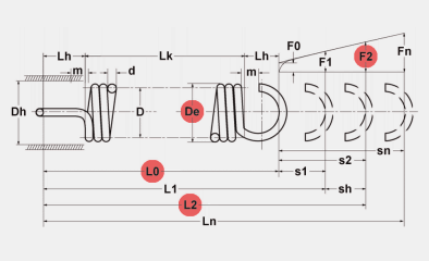 |
| Di = inner coil
diameter (mm) |
| De = outer coil
diameter (mm) |
| F0 = initial
tension (N) |
| L0 = unstressed
spring length (mm) |
| L1 = prestressed
spring length (mm) |
| F1 = prestressed
spring force (N) |
| L2 = loaded
spring length (mm) |
| F2 = loaded
spring force (N) |
|
 calculation according to dimension calculation according to dimension |
In this case for a
better overview, only the windows for the calculation according to dimensions
are available.
|

|
| d = wire diameter
(mm) |
| Di = inner coil
diameter (mm) |
| De = outer coil
diameter (mm) |
| F0 = initial
tension (N) |
| L0 = unstressed
spring length (mm) |
| L1 = prestressed
spring length (mm) |
| L2 = loaded
spring length (mm) |
| n = number of
coils (pc.) |
|
|
| result page
compression spring calculation |
Once the computation has been
started from the "Pre-settings", switch automatically to the "results"
computing page which displays all the computed spring sizes.
To
complete the calculation you are requested here to select the wire diameter
< d > according to DIN EN 10218-2 and adapt the number of coils < n > and
loops accordingly if required. The selection of wire diameter is compulsory.
The nearest five values are available for selection in the drop-down lists. In
the case of extension springs, the loop position (angle of rotation between the
two loops) is changed by adapting the number of coils < n >.
The values entered from the "pre-setting" and the wire diameter <
d > can be altered; they are displayed in white highlighted input fields.
All other values are purely output values. The spring is recalculated on the
basis of the modified values using the calculate button.
Invalid or
faulty calculation results are displayed for you in the text box. Solution
possibilities will be presented to you if you click on the individual fault
messages.
Important
The
tension coefficient "k" is incorporated as standard for the extension spring
computation. The tension coefficient "k" takes approximate account of the
maximum computed tension of the spring body.
Further functions of extension spring
calculation
Loop adjustment
The "loop adjustment" shows all properties and values of the selected
loops; it is automatically displayed in the current Extension spring design.
Adjustments are
carried out as follows:
For computations in which
the unstressed spring length < L0 > and the loop heights < LH1, LH2
> are not predefined, the loops heights are computed using a defined factor
for the corresponding loop shape. Aou can adjust these predefined values as
required, the correction is applied along the unstressed spring length < L0
>. However, when making the alteration please note the structural limitation
of certain loop shapes (e.g. 1/1 german loop: Lh = 0,8 to 1,1
Di).
For computations in which the unstressed spring length < L0 >
and the loop heights < LH1, LH2 > or just < L0 > are predefined, an
"actual value" and a "nominal value" is computed in the loop adjustment. The
function < centralise LH1, LH2 > enables you to align the "actual value"
to the "nominal value". Here again please note the structural limitation of
certain loop shapes. If necessary alter the loop shape.
Diagrams
The diagrams function provides you with the path-force diagram and
the Goodmann diagram in the case of dynamic calculation. |
You can print the calculation
or send it as an inquiry direct to Gutekunst Federn. When you have sent your
inquiry you will receive a copy of your inquiry back directly by
e-mail.
You can search our catalogue range directly for a
suitable spring using the < Search catalogue > function. As a standard,
the search program works with a tolerance value of 10%. Please note that our
catalogue springs are only supplied in the materials EN 10270-1 and EN
10270-3-1.4310. |
|